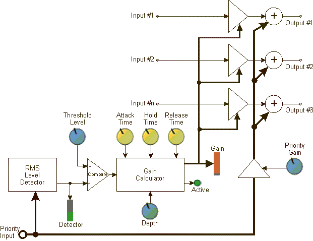
The Priority Ducker is used to attenuate one or more channels of audio input when the audio input of a “priority” channel reaches a specified Threshold. The audio on the Priority channel is then mixed to the outputs in place of, or louder than, the attenuated audio (refer to the diagram below). Using the controls provided in the Control Panel, you can control:
The Priority Ducker can have from 1 to 512 audio inputs and 1 Priority channel. There are three pre-set Detector Times, or you can choose the manual control. The Priority channel is the last input on the left side of the Priority Ducker Component.
A typical application would be for emergency announcements; when an emergency announcement begins, all of the other channels are reduced in gain and only the emergency announcement is heard.
|
Control |
Function |
Default/Range |
|---|---|---|
|
In Gain (dB) |
Controls the input Gain of the Priority channel. This control has no effect on the main channel inputs to the Priority Ducker. |
Default = 0 Range = -20 to 20 |
|
Response Panel |
Response graph: The x-axis represents the RMS Level Detector level. The y-axis represents the gain of the main inputs. |
X axis -60 to 20 Y axis -60 to 20 |
|
Detector (dB) |
The Detector meter monitors the RMS Level Detector level. |
Level meter |
|
Bypass |
The Bypass button bypasses the In and Out Gain controls. |
Off/On |
|
Control |
Function |
Default/Range |
|---|---|---|
|
Threshold Level (dBFS) |
The Threshold Level is the RMS level of the Priority channel at which the Priority Ducker activates. |
Default = -20 Range = -60 to 20 |
|
Depth (dB) |
The Depth sets the amount of attenuation applied to the main input channels when the Priority Ducker is activated. The Priority channel is mixed with the main outputs, so the Depth setting controls how much of the main channels are heard in the output. Setting the Depth to 60 dB of attenuation essentially mutes the main channels. |
Default = 100 Range = 0 to 100 |
|
Priority Gain (dB) |
The Priority Gain controls the output gain of the priority channel. Adjust this gain to the level you wish the priority channel to be heard when mixed to the outputs with the attenuated audio. |
Default = 0 Range = -100 to 20 |
The time constant is the time it takes to cover 63% of the control change. For Attack, the start gain is 1.0 (unity) and the end gain is 0. After 10 seconds, the value is at 1-0.63 = 0.37, which corresponds to -8.7 dB. For Release, the start gain is 0 and the end gain is 1.0 (unity). After 10 seconds, the value is at 0.63 which corresponds to -4 dB. Depth is ignored in this calculation, it simply limits the filtered gain to a minimum.
|
Control |
Function |
Default/Range |
|---|---|---|
|
Attack Time (milliseconds seconds) |
The Attack Time is the time it takes the main channel output to fall to 63% of the Depth level when the Priority Ducker is activated. |
Default = 10 ms Range = .100 ms to 10 s |
|
Hold Time (milliseconds |
The Hold Time determines how long the main channel stays at Depth once the Detector level drops below the Threshold. |
Default = 100 ms Range = 1 ms to 30 s |
|
Release Time (milliseconds seconds) |
The Release Time is the time it takes the main channel output to return to 63% of its normal level when the Priority Ducker is deactivated and the Hold Time expires. |
Default = 100 ms Range = 10 ms to 10 s |
|
Detector Time (milliseconds) |
The Detector Time control is available when you have selected Use Control for Detector Time in the Properties. The Detector Time determines the rate of change of the Detector level in response to changes in the Priority input signal. |
Default = 5 Range = 0.1 to 100 |
|
Control |
Function |
Default/Range |
|---|---|---|
|
Applied Gain (LED) |
The Applied Gain LED lights when the RMS level of the Priority channel exceeds the Threshold Level, that is, when the Priority Ducker is activated. |
Off/On |
|
Applied Gain |
The Gain meter represents the amount of gain applied to the main channels. |
Level meter |
|
Out Gain |
Control the Gain of the overall output of the Priority Ducker, both Priority and main channels. |
Default = 0 Range = -20 to 20 |
|
Property |
Function |
Choices |
|---|---|---|
|
Channels |
Sets the number of available channels for the Priority Ducker. |
1 to 512 |
|
Detector Time |
Selects a preset Detector Time, or enables the Detector Time control in the Control Panel. |
Use Control 10ms 20ms 50ms |
|
Bypass Gain Meter |
When set to Active, the Applied Gain meter is active regardless of the state of the Bypass button. This means you can adjust the Priority Ducker in Bypass mode. When set to Inactive, the Applied Gain meter is inactive to indicate that the component is in Bypass mode. |
Active / Inactive |
|
Pin Name |
Value |
String |
Position |
Pins Available |
|---|---|---|---|---|
|
Active |
0 1 |
false true |
0 1 |
Output |
|
Applied Gain |
00 to -40 |
0 dB to -40 dB |
0.000 to 1.00 |
Output |
|
Attack Time |
0.0005 to 10.0 |
5.00 ms to 10 s |
0.000 to 1.00 |
Input / Output |
|
Bypass |
0 1 |
Active |
0 1 |
Input / Output |
|
Depth |
0 to 100 |
0 dB to 100 dB |
0.000 to 1.00 |
Input / Output |
|
Detector Level |
-100 to 20 |
-100 dB to 20 dB |
0.000 to 1.00 |
Output |
|
Detector Time |
0.0001 to 0.1 |
.100 ms to 100 ms |
0.000 to 1.00 |
Input / Output |
|
Hold Time |
0.001 to 30 |
1.00 ms to 30 s |
0.000 to 1.00 |
Input / Output |
|
Input Gain |
-20.0 to 20.0 |
-20.0 dB to 20.0 dB |
0.000 to 1.00 |
Input / Output |
|
Output Gain |
-20.0 to 20.0 |
-20.0 dB to 20.0 dB |
0.000 to 1.00 |
Input / Output |
|
Priority Gain |
-100 to 20 |
-100 dB to 20 dB |
0.000 to 1.00 |
Input / Output |
|
Release Time |
0.010 to 10 |
10.0 ms to 10 s |
0.000 to 1.00 |
Input / Output |
|
Threshold Level |
-60 to 20 |
-60 dB to 20 dB |
0.000 to 1.00 |
Input / Output |
© 2009 - 2016 QSC, LLC. All rights reserved. QSC and the QSC logo are trademarks of QSC, LLC in the U.S. Patent and Trademark office and other countries. All other trademarks are the property of their respective owners.
http://patents.qsc.com.
![]()
 Related Topics